During the war the main advances in the weapons carried by the Infantryman were the introduction of the sub-machine gun and more power infantry anti-tank weapons. What follows is a brief summary of the Ordnance used by the various Infantry Regiments that served in the Division during the Second World War
Pistols
The British Army used a number of different pistols throughout the war but the main ones are listed below;
Enfield .38 No. 2 Mk I* revolver
This weapon served from 1936 to 1957 and was derived from those that served in the First World War. It weighed 0.780 kg, and was 264mm long. It held six .38 calibre cartridges in cylinder, with a double action trigger. It had a practical range of 30 metres. It had stiff trigger action and was generally regarded as
inaccurate.
Enfield
Revolver
9-mm Browning Hi-Power automatic pistol
This was a Belgian weapon, which was mass-produced in Canada during the war. The Browning saw widespread use in allied forces during World War II and eventually adopted as official in 1957 and is still in use today. It weighed 32oz, and was 8 inches long. The barrel length is 4.75 inches. The Browning uses a 13 round magazine in handle of 9mm calibre rounds.
.38 Smith and Wesson revolver.
This was a lend-Lease weapon from America, being modified to take the .38 British cartridge. The Smith and Wesson was 10.13 inches long with a 4 to 6 inch barrel. It weighed 1lb 8oz and has a 6 round revolving cylinder magazine holding .38 calibre rounds.
.45 Colt Automatic M1911 and M1911 A1
This was again a lend-Lease weapon from America. This Colt weighed 1.255kg with a loaded magazine, carrying seven .45 calibre rounds in the magazine. It was 216mm long, with a practical range of 30m.
The Lee-Enfield was a derived from the earlier Lee-Metford rifle and was developed due to the fact that when smokeless cordite was replaces compressed black powder in
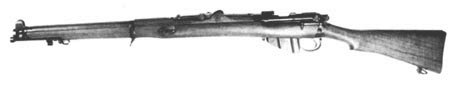
1892, it was found that the shallow rifling on the Lee-Metford has a comparatively short life, as the cordite eroded it. The Enfield rifling had five groves and at first the older Lee-Metfords were re-barrelled. However, in 1901, a Small-Arms Committee recommended that a short rifle suitable for both cavalry and infantry us was evaluated After, trialing a total 1000 rifles with 5-in shorter barrels, plus different loading systems, the short rifle was approved for service in December 1902. It became known as the Short, Magazine, Lee-Enfield, Mark I, or SMLE for short (pictured right). This was the most famous rifle ever produced by Britain and probably the finest bolt action rifle of its day. It was a short handy weapon, with almost classic lines and the feel gave a trained shooter great confidence.
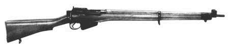
It served with British and Commonwealth forces during all of the First World War and in the early days of the war enable to BEF to produce the "mad minute", which caused the Germans to believe the British had more machine guns than they actually did, purely due to the weight of fire the troops were able to lay down. Modifications were made during the First World War to ease production and in 1916 a Mark III* was produced, which was the first to omit the magazine cut-off. The SMLE was remarkably resistant to dust and dirt and in the Second World War, it was still preferred to the later number 4 (pictured left), in the Western Desert. Commonwealth countries, which normally adopted British Army weapons retained the SMLE throughout the war and were greatly envied by the British units.
The rifle used a 0.303-in rimmed round, which could cause problems with loading, and although a rimless cartridge was available stocks of the rimmed version were so high it was not replaced until 1959. The rear sights for the SMLE were an open type, which required a lot of training in its use, whereas the later Number 4 used an aperture sight instead. Finally, the bayonet for the SMLE was large and heavy for the type of fighting that took place in the Second World War, compared to the trench battles of the First. It was due for replacement in the 1920's but funds were not easily available and thus it remained in service for years to come.
In the 1920's the design was altered to simplify the rifle and the Number 4 became the successor to the SMLE, being accepted into service in 1939. This rifle had two major changes from the SMLE, the first of which was the aperture back sight and the second being the absence of nose cap. By this about 3-in of barrel was left uncovered at the muzzle. A sniping version, fitted with telescopic sights, of the Number 4 was produced and this remained in service after the war, with NATO into the late 1970's but was re-barrelled to 7.62mm (0.300-in). Towards the end of the war a new "spike" bayonet was produced to the Number 4, but it proved unpopular, as it was useless as a knife, general tool, or even a tin opener and as such was not very daunting attached to the end of a rifle.
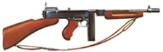
Brigadier-General John Thompson of the US army developed this weapon, from a machine pistol he designed during the First Work War. The first production models were made in 1921 and were called the M1921, which set the pattern for all subsequent types. It had a rectangular receiver, a finned barrel and pistol grips for both hands, along with a wooden stock. The bolt had a reduced diameter forward section, with the cocking handle on the top, slotted so that the sight line could pass through it. The magazine was a box a drum type, holding 20 or 50 rounds respectively.
Through its use by the US Marines in Shanghai and other actions, it became noticed outside the USA, although its use notorious by gangsters had made it famous through the press and motion pictures. In 1939 the British and French governments over 130,000 guns, as war clouds loomed of Europe. In June 1940 Thompson died, just as his weapon was achieving worldwide recognition. In 1940 the model in production was the M1928A1, fitted with a muzzle compensator. At $270 each it was expensive for the day, but by 1942 the cost had reduced to $70. In order to reduce the cost further the replacement of the Blish breech block by using a simple gas blowback system was proposed and in 1942 this version, now called the M1, was produced. Eventually 1,750,000 guns were produced, with enough spares to make another 250,000 guns also being made.
The gun was found in all theatres of the war, with the worst anyone saying about was that it was heavy! It became legendary for
its superb reliability, accuracy and resistance to hard conditions and it was preferred by allied servicemen over virtually every other sub-machine gun, except possibly the Australian Owen Gun.
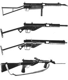
In 1940 Britain was in grave danger of invasion and every type of weapon was scare. The only sub-machine guns available were the US made Thompsons (details above) and a copy of the German MP28, made by Lanchester, which was too expensive for mass production. In 1941 the design department of the Royal Small Arms Factory produced a prototype of a new gun based on the Lanchester design and some capture German MP40. This new sub-machine gun made use of stampings and easily sub-contracted components. The gun was attractively light, compact and with a limited endurance trial of 5000 rounds, proved the soundness of the design. It was named the STEN, taking its name from the surnames of the two designers (Major R V Shepherd and Mr H J Turpin) who did most of the detailed work and the location of the Enfield factory. The overriding requirement was for a simple design and use of readily available materials and the resulting gun may have horrified some traditional gun makers since it was crude in the extreme. But it worked! The Mark I had a number of elaborations, such as a folding forehand grip, a conical flash-hider and some wooden furniture. However, the basic mechanism set the pattern of over 3 million to be made.
The blowback system used a heavy bolt and a fairly strong return spring, but this combination gave a rate of fire of about 550 rounds per minute, and more importantly ensure that the work parts were tolerant of dirt, dust, snow, mud and general neglect! The barrel was short and was held in a tubular metal sleeve and the body was another similar metal tube. The only machined parts were the bolt and barrel, with everything else being pressed or stamped, with all joins being welded or pinned. This meant most of the manufacture could be placed with small machine shop around the country, with the parts only be gathered at the larger factories, with the barrels/bolts, for final assembly and test.
The Mark I was soon replaced by the Mark II, which was the most famous of the series. The Mark II had all the frills removed and utilised a single tube stock with a flat plate on the end for the shoulder. The woodwork and grip from the Mark I were dispensed with and the barrel was held in by screwed jacket, which meant it could easily be removed. The magazine housing could be rotated to lie in line with the trigger mechanism, while a spring stud held on the stock.
Prior to D-Day the Mark III was available, with yet more simplifications, including a gun which had a fixed barrel and the body and jacket all in one. However, this version was not produced in great numbers, as moves were afoot to produce versions with following stocks for use by the airborne forces.
Despite it’s many advantages the Sten was not well liked by the men who used it, as the magazine gave some trouble, which could cause a jam. The magazine was never improved but in 1944 the Mark V was brought out to convince the troops a better version was available. The Mark V has a wooden butt and pistol grip and if the design of the magazine had been changed it could have been one of the best sub-machine guns of the war. (The picture left shows the MK I, II, III and V, from top to bottom.)
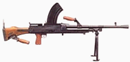
In the 1930's the British Army was looking for a replacement for the Lewis gun of First World War vintage. The British military attaché in Prague provided any enthusiastic report on a new Czech light machine gun, being produced by the State Armament Works in Brno. Surprisingly the War Office took note and after exhaustive tests lasting two years a manufacturing licence was sought.
The British wanted one or two changes before accepting design, such as using a 0.303-in rimmed cartridge instead of the original 7.92mm rimless one, and this may have not been advantageous. Other minor changes included a new butt, the removal of the cooling fins and a change to gas block. The first gun was manufactured in 1937, at the Small Arms Factory, Enfield and by July 1938 production was in full swing at 300 per month and it stayed at 400 per month for the rest of the war. The name Bren was derived forma combination of Brno and Enfield. Enfield was the only factory in Britain tooled up to make the gun, until Inglis in Canada, started production in 1943, which meant that one successful bombing raid in 1940 or 1941 could have been disastrous.
The Bren was an excellent light machine gun, being simple, strong, accurate and easy to fire. It was remarkably free from stoppages and other vices. It was a gas-operated weapon, using a long-stroke principle. The barrel was removable and locked to the body by a quick release nut. The gas block was on barrel and mated with the gas cylinder, which is below the barrel, but the block could be drawn outwards. Changing the barrel was both quick and easy, as the carrying handle is on the barrel, thus reducing the risk of burns. It was recommended that the barrel be changed every three magazines to allow the hot barrel to cool beside the gun. The gas cylinder had a long piston inside which ran back in the body and carries the return spring. The breech block rides on the piston extension and locked by tipping its rear end into contact with lugs on the body. Apart from the trigger mechanism there are few other working parts.
The magazine held 30 rounds and fed vertically downwards, and thus the sights were offset to the left side. The magazine was one of the weak points as it was essential that each round be fed in with its rim behind the one on front. Failure to do this with even one round caused a stoppage, though easily cleared. The magazines were also sensitive to damage, which could also cause a stoppage. Apart from this virtually the only other thing to break on a Bren Gun was the occasional firing pin.
The gun was an immediate success and it entered service as the Mark I in August 1938, and in 1941 a Mark II was introduced. It was simplified MK I on which the bipod legs no longer telescoped, the drum rear sight was changed for a ladder type and the butt-strap and lower pistol grip being discarded. This reduced the gun's weight, which was further reduced again in 1943 and 1944 along with a slightly shorted barrel. The Bren gun stayed in front line service until 1958, when the 7.62mm (0.300) rimless cartridge introduced.
There were several attempts to extend the role of the Bren, which included
its use as an Anti-aircraft weapon (in single, double or quadruple mounts), sometimes with a drum feed of 100 rounds, which was not a success. Originally, every gun had a complex and heavy tripod alternative mount, which was unpopular. Most of the stocks of this mount were lost in the fall of France and were never replaced.
In 1940 it was fitted to home defence armoured cars and the famous infantry carrier, which was better known as the Bren Gun Carrier, although it was rarely used in this role. The Bren was a gun was designed to be the main firepower of an infantry section and when used that way it was amongst the best guns of
its kind ever produced.
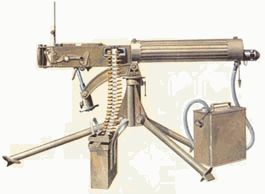
In the early 1900's Vickers saw that the earlier Maxim gun was capable of improvement and development, bringing out their own version in 1904. The new gun was lighter than the Maxim as weight had been saved by carefully calculating where the most stress was. This along with high grade steels and aluminium also reduced the weight. The toggle action was turned upside down, which reduced the depth of the receiver by almost half, which, with the other measures, reduced the weight of the gun by nearly 25%.
It was adopted into service in 1912 and earned a good reputation for
reliability and effectiveness during the First World War, with the British Army
forming Battalions armed with now else, but the Vickers. One point of interest
is that during tests it once fired non-stop of seven days! The main drawback
with the Vickers was that it needed a crew of three to move it, as it was heavy,
as well as a supply of water (to cool it) and men to make up the ammunition
belts. The gun weighed 40lb and the Tripod another 60lb. Normally each battalion
was equipped with two Vickers with the Support Company.
In the 1920's and 1930's heavy version was made in 0.5-in (12.7mm) calibre, for use in Tanks, such as the
Matilda I and the MKVI Light Tank. The basic Vickers Gun remained in service with The British Army until the mid-1960's.
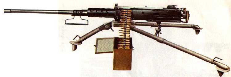
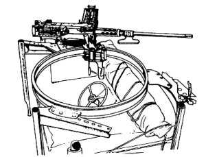
The M2HB is a Browning 0.5 inch calibre American heavy machine gun, produced since 1933 and mounted on American military vehicles since the Second World War. It is still in service to this day. It has a muzzle velocity of 890m/s and fires ball ammunition at 450-500 rounds-per-minute fed by a belt system. The gun originally appeared as a water-cooled anti- aircraft machine gun, but in the 1930s the M2 air-cooled version was developed for use on tanks.
Although, it could also used on a tripod by infantry, the British Army mainly
used the 0.5 inch Browning mounted on vehicles, such as Half Tracks, Tank
Destroyers and Self-Propelled Guns. In Belgium, in 1944, one Queens Regiment
Bren Gun carrier actually mounted three 0.5 inch Browning's, to increase its
fire power. The picture below shows a typical vehicle mount.
The British Army used a few different types of hand grenades an the below list gives some basic information on each
British No.36 (Mills) Grenade
This was a continuation of the weapons developed during the First World War and was used throughout the Second World War. Although normally thrown it was also sometimes used as trip-wired Anti-Personnel Grenade.
British No.69 Grenade
This was gravity Grenade, which when thrown caused the safety tape to be pulled clear by a weight and caused the Grenade to explode on impact and was made of Bakelite.
No.73 Anti-Tank Hand Grenade
Known as the Thermos bomb, it was a purse blast weapon that was more commonly used for demolition work.
No.74 (ST) Anti-Tank Hand Grenade
Also known as the Sticky bomb, as it has a sticky coating that made helped it stick to the target. It was unpopular as it could stick to anything and was used as little as possible, plus it meant the user had to virtually touch the tank to use it.
No.75 Anti-Tank Hand Grenade
Also known as the Hawkins Grenade, this weapon was intended to be either
thrown or laid as a mine to blow a tank's track off. It utilised a crush igniter
fuse with half its weight being made up of the bursting charge. It was often
used in clusters for better effect.
No.77 WP Grenade
This grenade was always used with an impact fuse, and was filled with white phosphorous. The latter could cause severe burns and possibly ignite buildings.
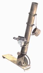
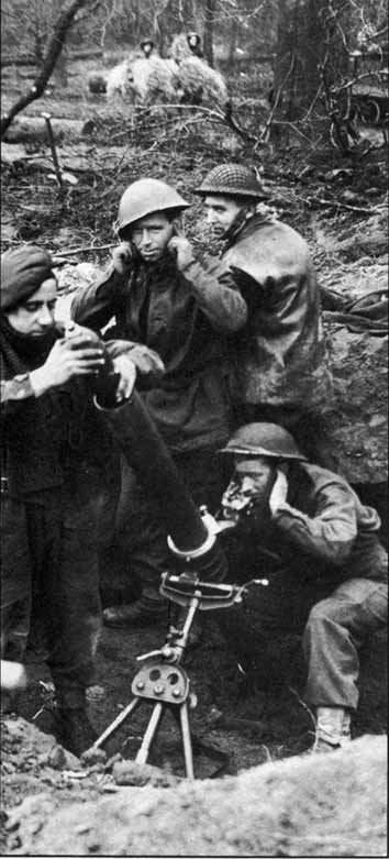
The 3-in (76mm) Stokes mortar was first offered to the British Army in 1915, but due to the number of such weapons available it was some type before they committed themselves. They were originally concerned about using a tumbling bomb, but Stokes then developed and proved a fin stabilised bomb. He arranged the firing pin so that it could be withdrawn and improved the sights. With this the 3-in Stokes Mortar entered service.
Between the wars the design of the Stokes mortar was modernised and better bombs provided. In the 1930's 2-in (51mm) mortars (right) were developed to replace the rifle grenade as a means of reaching out a little further than was possible with hand grenades and one was normally issued to each platoon, while the 3-in mortar (left) was issued to the support company. The 3-in mortar could fire HE and smoke, while the 2-in mortar was restricted to HE.
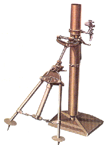
As
the war progressed it was realised that at heavier mortar was needed to provide
more support, especially for the infantry units and so the 4.2-in Mortar
(pictured left) was developed, based upon the Chemical Weapons Design from the
Great War. The British version differed from the US one as the latter had a
rifled barrel. The 4.2-in Mortar was a simple and rugged design and used a
wheeled base plate for easier movement.
It was first used in North Africa, by the Chemical Warfare Companies of the
Royal Engineers at El Alamein using conventional ammunition. However, from
about mid-1943 the Divisional Machine Gun Battalions (one per Infantry Division)
and Independent Machine Gun Companies (one per Armoured Division) were converted
to included one Mortar company or Platoon respectively operating 4.2-in mortars.
For an armoured division's Independent MG Company an extra platoon was added
with 4 mortars.
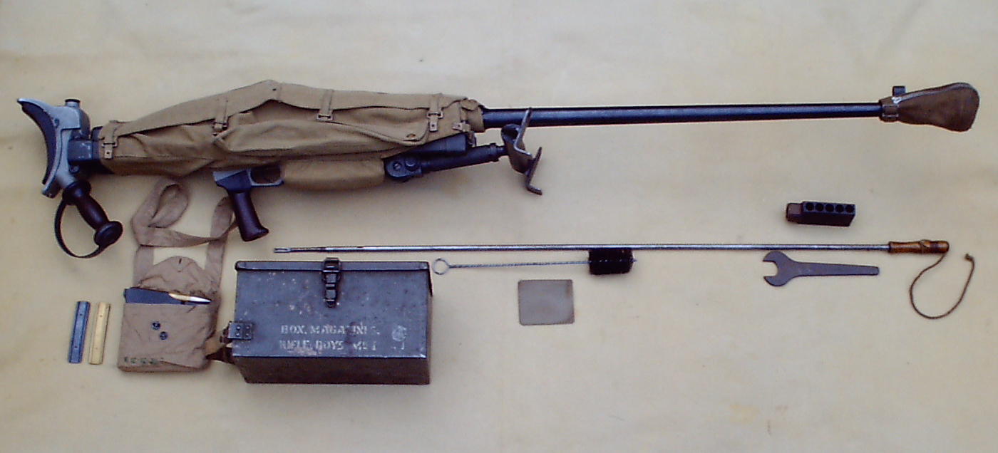
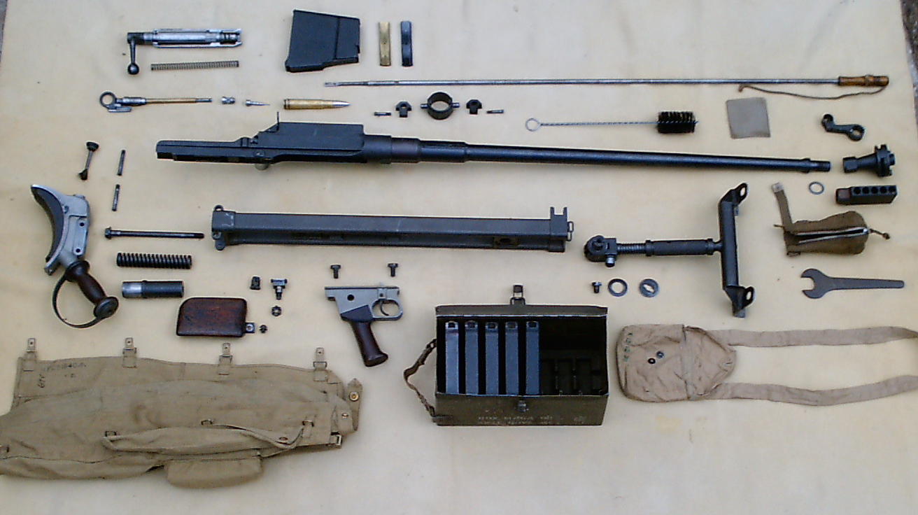
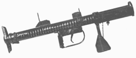
The Boys was the only anti-tank rifle to serve with the British Army. It was designed in the mid 1930's when this type of weapon was popular everywhere. It used a bolt action feeding from a top mounted magazine and it all
its parts were robust and heavy, but it did weight 36lb (16.5 kg) which was substantial load for one man to carry.
The barrel and breech were mounted on a slide which recoiled along the top of the stock and so absorbed some of the considerable force from the firing a 0.55-in (14mm) round. A muzzle break was also fitted to reduce the recoil still further. The weapon was supported on a monopod at the front and this too has a form of shock absorber built into it. The round was
based on a modified US .50 cal cartridge. The case had a belt added to make
headspace more easily set up and maintained and also to strengthen the case head
to withstand the firing stresses. The neck was expanded to .55 cal to allow a
heavier projectile to be used for better effect on armour. The bullet was steel cored, although later versions had a tungsten core.
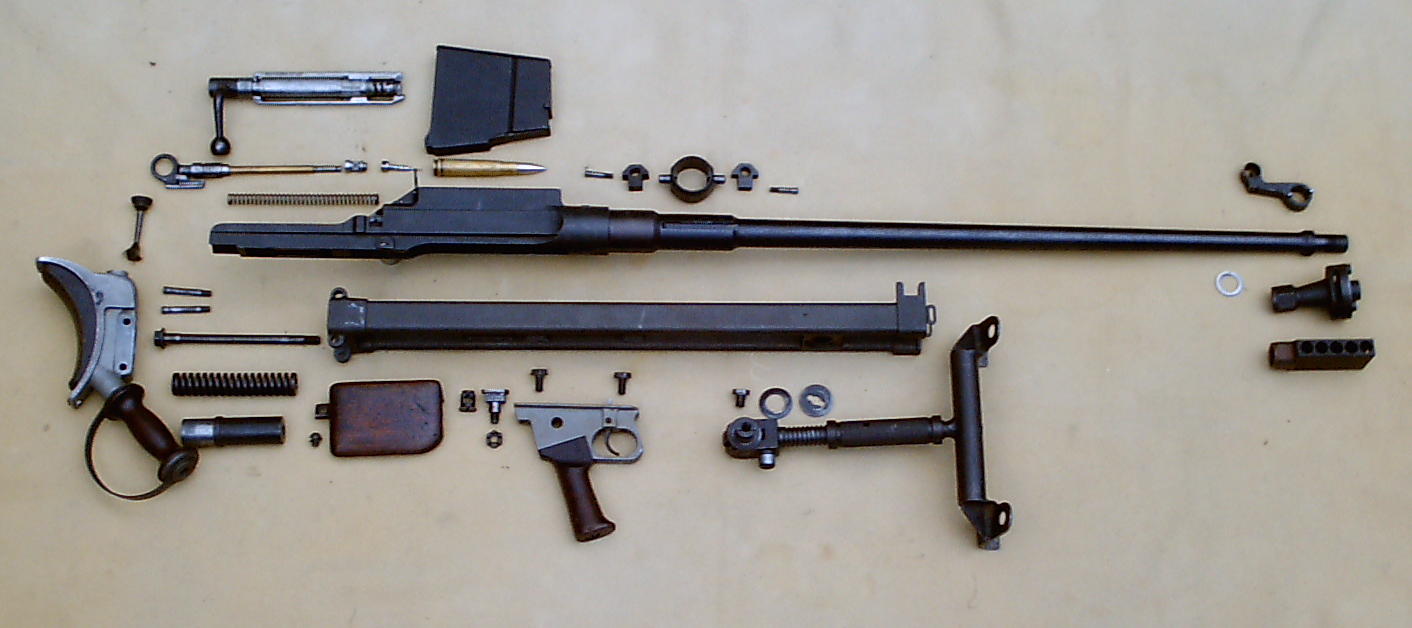
The pictures below show the Boys Anti-Tank Rifle with all its accessories and
also 'broken down'.
(Larger images can be obtained by clicking on each
of the ones below).
The armour penetration was never impressive and the Boys was virtually obsolete before it entered service. It did see action in France in 1940 and in Burma and Malaya in 1941-42. It was also mounted in armoured cars and Bren Gun carriers in Egypt and Libya in 1941, where it proofed a good anti-personnel weapon in rocky terrain when rock fragments were produced by indirect fire. It was eventually replaced by the PIAT in 1942.
By 1941 it was obvious that the Boys anti-tank rifle and the No. 68 Grenade, were no match against the German tanks, so some method of for launching a sizeable hollow-charge to a range of 100m (330ft) was needed. Additionally, the weapon had to be accurate enough to hit a moving tank, but in 1941 rocket technology was still in
its infancy.
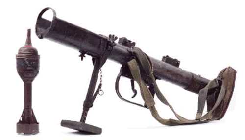
Before the war a retired officer, Lieutenant-Colonel Blacker, had made a number of cheap weapons in his own work shop, among which was a large spigot mortar, known as the Blacker Bombard. It was suggested that a smaller version of this could be used as an infantry launcher. So a few trial models were built, with the grenade being held in a trough on the front. This "grenade" had a hollow tail, flared to the rear and in the forward end a small cartridge was fitted. When the launcher was fired, a steel spigot was driven by a power spring to strike and detonate the cartridge, thus driving the grenade of the spigot. A cut away is shown below.
This arrangement was can be compared to a gun in which the "barrel" (the tail of the grenade) was projected, while the "shell" (the spigot) remained stationary. The spigot guided the grenade for the first few moments of flight, but the diameter of the bomb was not restricted by the diameter of the launcher barrel, thus allowing the PIAT to be made lighter than conventional mortars, while still launching a charge of equivalent weight and size. The name PIAT is derived from the initials of it’s formal name Projector, Infantry, Anti-Tank.
The spigot had to be cocked before the first shot, but thereafter the recoil from each firing re-cocked the weapon automatically, provided the user held the weapon firmly. There were a few snags with the PIAT, such as cocking for the first round being extremely difficult due to the strength of the spring. Also firing the PIAT the gunner held on to the trigger guard with his left hand, pulling back hard, and with the trigger being so stiff it took two fingers to operate it. After pulling the trigger there was a noticeable pause while the spigot shot forward. This could lead to unwary recruits loosening their grip and then receiving a massive blow to the shoulder as the grenade flew off. Then they found that the spring had not re-cocked. The gunner normally lay prone and despite stories it was never fired from the hip or shoulder while
standing, although Fusilier Frank Jefferson (2nd Bn. The Lancashire Fusiliers)
won the Victoria Cross whilst firing it from the hip in Italy from a distance of
20yrds against enemy armour. After he destroyed one tank, he re-cocked the
spring, re-loaded the PIAT and started to attack a second tank which withdrew!
The bomb (shown left next to a PIAT), weighing 3lb (1.4kg) was capable of penetrating the armour of German tanks of
its time and had a best fighting range of 100m (330ft) it was adequate. During the battle of Villers-Bocage the 1/7th Queens Regiment actually went "Tiger Hunting" with their PIATs in the town. The main benefit of the
PIAT not surpassed for 40 years was that it could be used from an enclosed space without risk to the firer. Thus it was used innumerable street battles, including the defence of the Arnhem Bridge. It could also be fired as a crude mortar, by tilting on its mount.
Some 11500 PIATs were produced, with it serving in all theatres of the war, It remained the standard infantry anti-tank weapon in the British Army until 1950, with one being issued to each platoon.
This gun was issued to the support companies from about 1943 onwards, to augment the Royal Artillery anti-tank role and bolster infantry anti-tank defence. To see details of this weapon please visit the 6-pdr anti-tank gun on the artillery page.
Apart from the many lorries used by the British Army throughout the war
(of which information on the Morris CS series is provided), there were two other
key modes of transport used by the infantry to go about their business. These
are the Universal Carrier and the Half-Track.
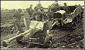
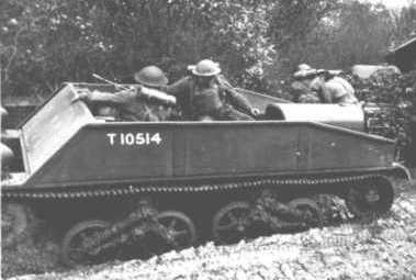
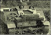
Universal Carrier:
At the start of the war there many different types of this vehicle in service, including some made by Loyd and what was to become better known as the Bren Gun carrier.
After the fall of France the British Army rationalised the equipment used by
mobile infantry sections and settled up the Bren Gun carrier for use as an
section transport or light gun tractor. Although it was called a Bren Gun
carrier it was seldom actually armed with one, but rather it could carry a
Vickers Medium Machine Gun (favoured by the Australians), a Boys Anti-tank
rifle, a 2" or a 3" mortar. It served with the Carrier Platoons of the
Motor Battalions with aim of providing andInfantry Battalion with the
ability to move a small portion of its establishment under armoured protection.
The men of the Rifle Platoons could not pile into the vehicles as they could do
with half-tracks. Each Carrier had its own Bren gun team and was intended to
operate in a fire support role for the walking infantrymen, rather than act as
their transportation. In reality, the Carrier served in a host of other less
offensive but equally vital roles. Where a Carrier Section of three machines was
placed under the command of a Rifle Company, the Company Commander could utilise
it in a number of ways.Firstly, he
could take advantage of the addition of three more Bren guns, a PIAT and a 2
inch mortar to ‘thicken the fire of his Fire Platoon’.This unit provided a base of fire under cover of which the remaining two
Rifle Platoons would advance.The
support weapons of the Carrier Section could literally double the firepower of
this Platoon.
Later in the war, after the Normandy invasion a flame-thrower variant,
called a Wasp, (shown right) was also produced, in which the flame gun was fitted
in place of the MG and fuel tanks installed in the rear compartment, with a
higher armoured box. Another Wasp variant (MK II), developed by the Canadian
Army had the fuel tanks mounted at the rear outside a smaller modified rear
compartment. This allowed a third crew man to return with his Bren, firing from
the rear troop compartment though as the flame gun was still on the MG position.
This improved Wasp MK II variant quickly took precedence over the earlier model.
In another development a larger flame gun fitted to the left of the gunner's
position. The 'Wasp' began to be issued to Motor Battalions in late 1944 and was
used by the Rifle Brigade in the Division during the crossing of the Rhine in
1945.
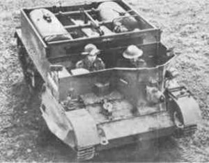
The other carrier to be developed mainly as a small gun tractor was the Loyd carrier. The Loyd carrier was mainly used as an infantry transport upto 1943, until it was adopted as the standard vehicle for role of towing the 6-pdr and 4.2-in mortar. It was designed to have armoured plates
attached; to improve protection, but this were rarely fitted. Unfortunately there was little carrying space inside
(see below), that two carriers were needed to accommodate a 6-pdr anti-tank gun and crew, in one, and the ammunition, in the second.
As shown by the picture to the left one of the main drawbacks with all the Universal carriers was that they offered no protection from the weather, although some rudimentary covers were used by the crews.
Universal
Carrier
Loyd Carrier
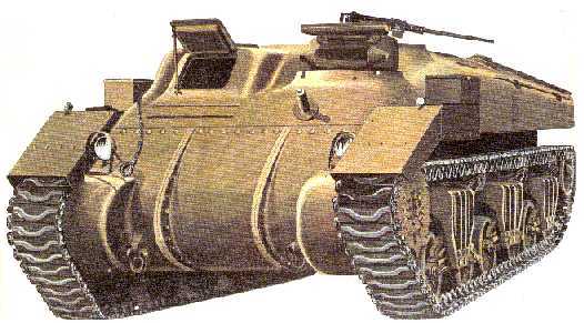
Bren Gun Carrier MK I, Specification:-
Armament:
Various:
0.303 Bren Gun or 0.303 Vickers Gun, or Boys A/T Rifle, plus 2 x 0.303 Rifles
The 15 cwt CS8 Morris-Commercial was first developed in 1934. The British WD
had a need for a general purpose vehicle of around 15 cwt capacity and MCC in
co-operation with the WD designed a new truck using many parts from their new
1933 civilian C series range. The new MCC WD truck was designated CS8, (S
meaning 6 cyl and 8 meaning approx. 8 ft wheel base) it had a short stubby
appearance and high ground clearance. The CS8 evolved into the ubiquitous
15 cwt general purpose truck that was eventually built by other British
manufacturers such as Guy, Bedford, Commer and Fordson. The 15 cwt range of
vehicles became the backbone of the British army. The CS8 was built in three
Mark's until approx. 1942 when a 4 cyl variant, the C4 model replaced it.
Early CS8's had small Aero Screen and canvas doors, which were
eventually replaced by a full windscreen, and metal skinned half doors on the
last production vehicles around 1941. The C4 was essentially the same truck
as the CS8 and was built in two Mark's (different wheel bases), it was
fitted with a full windscreen and metal doors like the late CS8's. The
CS8/C4's were eventually replaced by the 4 cylinder 4X4 C8 quad models
that began production during 1944; these were based on the earlier
The CS8/C4 was seen in many different roles including Office, house wireless,
water tanker, petrol bowser, 2-pdr portee, and compressor. The lengthened CS8 chassis was used as the basis of the
CS9 Armoured Car. Approx. 100 of these were built. Some served with the BEF in France and others in the North African desert where their excessive weight and 4x2 configuration was a drawback.
As the war progressed more specialised forms of
infantry transport were developed especially for the Lorried Infantry of
Armoured Divisions. These were known as Troop Carrying Vehicles (TCV).
Effectively very large lorries, two RASC drivers
took it in turns to drive each massive TCV. They were top heavy and yawed
frighteningly at speed, particularly when cornering. Usually they were cold and
draughty, but when the canvas screens were folded they were warm and cosy. Here
the infantry could doze, play cards, and eat there 'compo' rations en route to
the next engagement. As the moved an 'air sentry' sat on the roof, within the
circular lid for the Anti-aircraft Bren gun for defence against air attack.
Inside there were two rows of tip-up seats facing inwards and a central row
facing out in alternate directions. The TCV was high-sided, and the sides were
un-armoured, which made it highly vulnerable to any enemy activity. The two
doors at the back opened outwards with a mounting step on left and right, to
allow quick disembarkation and loading.
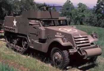
The development of the half-track was a major step in mechanised warfare as it allowed the infantry supporting the tanks to accompany them in a semi-tracked vehicle with armour protection.
The White M3A2 half-track was the most widely used half-track of the war, being developed from the M3A1 Scout car. It could carry 12 men, plus 2 crew and mounted either a 0.5-in Browning Machine Gun or 0.303 Bren Gun
(with the latter favoured by the British) for self defence. Like the White Scout
Car most models has an unditching roller or winch (10,000 lb capacity) attached
to front. A development of variant of the M3A2 was the M5A1 and had an M49 ring
mount for the machine gun and could carry 13 passengers. The M5 variant had
bodies with rounded rear corners while the M2 and M3 were square and also had a
different type of armour fitted, which provided less protection from small calibre AP rounds, due to how the armour plate was tempered.
The Kangaroo Infantry Carrier was deployed by the British late in the war, having served in Northern Europe with the Canadians, since shortly after the Normandy landings.
During the attacks near Caen, the Canadian 2nd Corps were confronted by
strong German positions, to the Corps Commander, Lt-General Simonds, hit upon
the idea of using armoured carriers to put the infantry onto their objectives.
About this time 3 Canadian Artillery Regiments were re-equipped with towed
25-pdr guns as the barrels of their US Priest self-propelled guns were worn out.
Having obtained permission to convert the Priests into carriers the howitzer,
mantlet, seats and ammunition lockers were removed and a piece of armour plate
welded across the front opening. This work was done by an advanced workshop
detachment whose codename happened to be Kangaroo.
The conversion and operation were both a success and the term 'Kangaroo' was
then applied to any tank that was converted into an infantry carrier. Most
conversions were Canadian Sherman Ram's or normal Sherman tanks, with old
Priests and Shermans mainly used in Italy. The 79th Armoured Division took
responsibility for the Armoured Personal Carrier (APC) tasks, with 49th APC
Regiment being formed in late 1944. The Kangaroo was an overweight and
extravagant way of moving ten infantry, but it worked and used vehicles that
would otherwise have been scrapped. It also gave an insight into providing the
infantry with APCs, and several remained in service with the British after the
war until replaced by purpose built vehicles.
Specification:- None, as various vehicles were converted. The picture below shows a Sherman/Ram conversion, armed with a 0.50 calibre Browning.
 As
the war progressed it was realised that at heavier mortar was needed to provide
more support, especially for the infantry units and so the 4.2-in Mortar
(pictured left) was developed, based upon the Chemical Weapons Design from the
Great War. The British version differed from the US one as the latter had a
rifled barrel. The 4.2-in Mortar was a simple and rugged design and used a
wheeled base plate for easier movement.
As
the war progressed it was realised that at heavier mortar was needed to provide
more support, especially for the infantry units and so the 4.2-in Mortar
(pictured left) was developed, based upon the Chemical Weapons Design from the
Great War. The British version differed from the US one as the latter had a
rifled barrel. The 4.2-in Mortar was a simple and rugged design and used a
wheeled base plate for easier movement.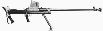

 Later in the war, after the Normandy invasion a flame-thrower variant,
called a
Later in the war, after the Normandy invasion a flame-thrower variant,
called a